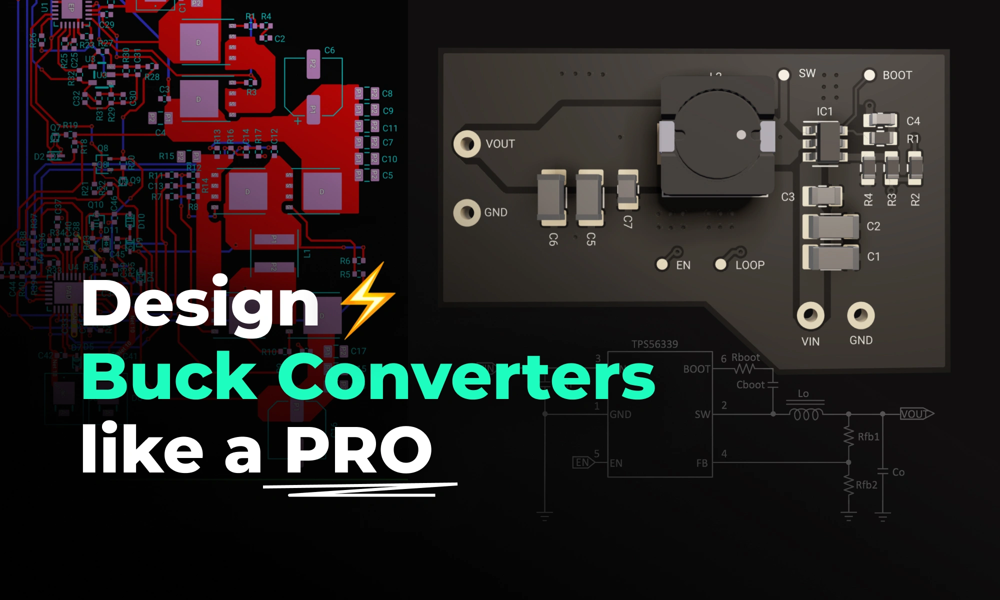
When you’re first diving into power-supply design, buck converters can feel a bit like magic boxes—take a higher voltage in, and out comes a perfectly regulated, lower voltage with impressive efficiency, minimal noise, and a tiny PCB footprint. Yet the true secret to a well designed converter isn’t just hidden in some arcane equation; it’s also the way you lay out copper on your board.
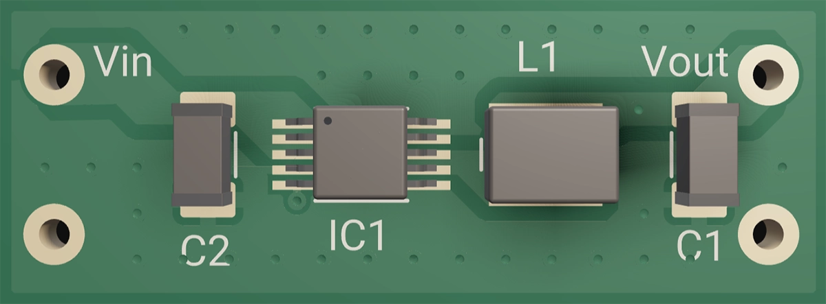
At its heart, a buck converter is nothing more than three core elements working together to regulate a higher voltage to a lower voltage—and understanding these will make everything else click.
The Fast Switch (MOSFET) This semiconductor turns your input voltage on and off hundreds of thousands—or even millions—of times per second. By varying the duty cycle (the fraction of time “on” versus “off”), it controls the average energy delivered downstream.
The Inductor (“Energy Storage”) During each “on” phase, the inductor stores energy in its magnetic field; when you switch off, that energy discharges into the load. This pulsed exchange smooths out the current and sets the stage for a steady voltage.
The Capacitors (“Voltage Buffers”) Placed at the output (and often at the input), these absorb the inductor’s ripple and deliver bursts of current when your load suddenly demands it. Together, the inductor and capacitors form an LC filter that turns square pulses into a level, and ideally stable, DC voltage rail.
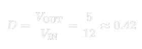
Here’s the simple math for a 12 V→5 V converter:
That 42 % duty cycle tells the MOSFET exactly how long to stay on each cycle so the LC filter averages out to 5 V.
Behind the scenes, a control IC monitors the output, compares it to an internal reference, and tweaks that duty cycle in real time to handle changing loads or input swings. But regardless of controller complexity, the switch + inductor + filter always remain the converter’s heart and soul.
Component Selection: Why It Matters (and How to Get It Right)
Pick the wrong inductor, and you may face problems like overheating, excessive output ripple, or even core saturation that starves your load under sudden demand. To help you choose wisely, here’s what every beginner EE should know about inductor characteristics:
Current Rating and Saturation (Isat) Every inductor has a maximum current above which its magnetic core saturates and loses inductance, causing large current surges. Aim for an Isat at least 1.2×–1.5× your peak load to ensure reliable performance under transient conditions.
DC Resistance (DCR) DCR is the winding’s inherent copper resistance. Lower DCR reduces conduction losses and heat buildup—boosting efficiency—but often comes in a larger or costlier package. Balance your efficiency goals with board space and budget constraints by selecting the lowest practical DCR.
Core Material The core defines how the inductor behaves across frequencies and currents:
Ferrite cores are the workhorses of switching converters, offering high permeability and low losses at high frequency. They deliver crisp switching edges and minimal ripple—ideal for most buck designs.
Powdered-Iron cores incorporate distributed gaps, giving a gentler saturation knee and better performance under high DC bias. Use them when your peak currents vary widely or when you need softer saturation behavior.
Shielded vs. Unshielded: Shielded inductors confine magnetic fields within their package, reducing EMI coupling to adjacent traces. Unshielded inductors can be more compact but may require extra clearance from sensitive circuits.
Package & Thermal Performance Inductor packages differ in footprint, height, and thermal dissipation. Compact surface-mount inductors save board space but may run hotter; larger through-hole or tall-stack types handle more power but occupy more real estate. Evaluate your thermal budget and mechanical constraints when selecting package size.
Pro tip:Choosing an inductor with a bit of extra saturation current rating and modestly lower DCR gives you valuable headroom during prototyping—preventing unexpected heat and ripple issues as your load conditions change.
Capacitor Mix
A combination of MLCCs and a bulk cap covers ripple from kHz to MHz—get this wrong, and you’ll hear audible squeals or see output spikes.
Capacitor Selection
| Type | Role | Placement | Pro Tip |
| :--- | :--- | :--- | :--- |
| MLCC | Kill high-frequency ripple | Within 1–2 mm of switch and inductor | Derate by ≥2×—X5R/X7R parts deliver only 40–60 % of marked capacitance under bias |
| Bulk | Reservoir for mid/low-freq. | Beside the output inductor | Watch ripple-current rating; its ESR provides a natural damping zero |
Deep dive: MLCCs lose capacitance under DC bias and heat. And yes, they can sing! Ensure parallel MLCCs are carefully secured mechanically to mute piezo effects. Placing smaller-value capacitors first help to attenuate the high frequency singing in the larger smoothing caps.
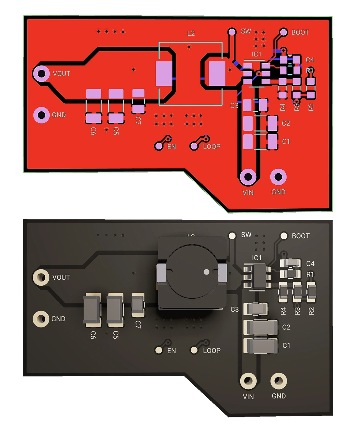
Having chosen your parts, layout is your next battleground. The difference between a noisy, inefficient converter and a clean, reliable one often comes down to copper placement. Follow these steps to keep that switching loop tight and your ground plane unbroken.
Remember: “Keep the switching loop tiny and the ground plane continuous.”
Minimize the Switch Loop
Sketch the loop: Input cap → High-side MOSFET → Inductor → Output cap → Return to input cap.
Goal: Loop area < 10 mm². Every extra mm² adds parasitic inductance, causing ringing, EMI, and wasted switching energy.
Tip: One customer saw a 20 dB EMI drop simply by shrinking their loop from 15 mm² to 8 mm²!
Use at least six short vias per cap or ground polygon. More vias lower impedance, spread heat, and tame high-frequency noise.
Separate Control Signals
Route gate-drive and feedback traces outside high-current loops. If intersections are unavoidable, shield with a small ground pour.
Different Buck Converter Topologies
From full DIY assemblies to one-click, ready-to-use modules, these different topologies trade off flexibility, board space, and time-to-market. Pick the one that fits your project rhythm.
| Topology | What You're Really Building | When to Use it |
| :--- | :--- | :--- |
| Discrete | Hand-select controller, gate driver, MOSFETs, inductor. Like building a bike wheel by wheel | Total flexibility, custom performance, or lowest part cost |
| [DrMOS](https://www.flux.ai/flux/tps62130argtr-regulator?editor=pcb_2d) | Integrated MOSFET + driver in one package—just add inductor and caps. Like buying a pre-built engine. | Mid-power designs, tight PCB area |
| [Power Module](https://www.flux.ai/flux/buck-boost-3p3v-500ma-physical-module) | Complete power stage: driver, MOSFETs, inductor, capacitors, telemetry—even PMBus. Ready-to-ride e-bike | Fastest path to market, highest integration |
Each template already includes polygon pours for power and ground, and via-stitching. Once cloned, customize only what matters.
Ground planes are a default in any Flux project, which reflows around all parts and pads to help with noise isolation. Polygons are now in Flux helping you leverage wide current paths for your output voltage to flow through. Adjust thermal reliefs, keep-outs, and copper weights without redrawing anything.
Stuck on compensation loops or gate-resistor values? Ask Copilot right inside the editor. It explains theory, suggests values, and even pulls tables from datasheet PDFs.
Zone off low-speed signals—UART, I²C, sensors—and let Auto-Layout handle them. That frees you to hand-route the critical buck loops that define performance.
“Copilot help me determine the best orientation of U1 to minimize the switching current loop.”
Quick-Reference Cheat Sheet
Think of this as your design checklist: tape it to your monitor, keep it next to your keyboard, or fold it in your notebook. Pull it up whenever you need a formula, a layout reminder, or a topology refresher.
Key Formulas & Practices
| Topic | Formula / Practice | Why it Matters |
| :--- | :--- | :--- |
| Duty Cycle (D) | D = VOUT / VIN | Sets the average output voltage |
| Inductor Ripple | ΔIL = (VIN–VOUT) · D / (fSW · L) | Balances ripple vs. transient response |
| Efficiency (η) | η = (VOUT · IOUT) / (VIN · IIN) · 100 % | Quantifies total losses |
| Switching Loss (Psw) | Psw = (Eon + Eoff) · fSW | Guides MOSFET choice and frequency |
| SW Loop Area | less than 10 mm²| Minimizes parasitic inductance and EMI |
| Via Stitching | ≥ 6 vias per capacitor | Lowers impedance and spreads heat |
| Grounding | Continuous plane under SW node | Prevents unintended current loops |
Topologies & Control Methods
| Aspect | Options / Methods | When to Use |
| :--- | :--- | :--- |
| Topologies | Discrete / DrMOS / Power Module | Flexibility vs. integration vs. speed to market |
| Control | Voltage-mode, Peak-Current, COT | Trade loop speed, stability, and complexity |
| Gate-Drive Tuning | Rgate: 2–5 Ω; Dead-time: 20–50 ns | Optimize EMI control vs. switching speed |
| Capacitor Mix | MLCC + Bulk (Ta/Poly) | Flat impedance across the frequency spectrum |
Ready to Build Your First Buck in Minutes?
Pick your topology above and click Clone in Flux.
Drag & drop your caps and inductor from the parts panel.
Invoke Copilot for any component or layout question.
Hand-tune your switch loops—and watch your efficiency and EMI metrics soar.
With Flux’s polygons, AI Copilot, and Auto-Layout, you’ll spend less time wrestling nets and more time optimizing your power stage—so you can ship faster and with confidence.
At its heart, a buck converter is nothing more than three core elements working together to regulate a higher voltage to a lower voltage—and understanding these will make everything else click.
The Fast Switch (MOSFET) This semiconductor turns your input voltage on and off hundreds of thousands—or even millions—of times per second. By varying the duty cycle (the fraction of time “on” versus “off”), it controls the average energy delivered downstream.
The Inductor (“Energy Storage”) During each “on” phase, the inductor stores energy in its magnetic field; when you switch off, that energy discharges into the load. This pulsed exchange smooths out the current and sets the stage for a steady voltage.
The Capacitors (“Voltage Buffers”) Placed at the output (and often at the input), these absorb the inductor’s ripple and deliver bursts of current when your load suddenly demands it. Together, the inductor and capacitors form an LC filter that turns square pulses into a level, and ideally stable, DC voltage rail.
Here’s the simple math for a 12 V→5 V converter:
That 42 % duty cycle tells the MOSFET exactly how long to stay on each cycle so the LC filter averages out to 5 V.
Behind the scenes, a control IC monitors the output, compares it to an internal reference, and tweaks that duty cycle in real time to handle changing loads or input swings. But regardless of controller complexity, the switch + inductor + filter always remain the converter’s heart and soul.
Component Selection: Why It Matters (and How to Get It Right)
Pick the wrong inductor, and you may face problems like overheating, excessive output ripple, or even core saturation that starves your load under sudden demand. To help you choose wisely, here’s what every beginner EE should know about inductor characteristics:
Current Rating and Saturation (Isat) Every inductor has a maximum current above which its magnetic core saturates and loses inductance, causing large current surges. Aim for an Isat at least 1.2×–1.5× your peak load to ensure reliable performance under transient conditions.
DC Resistance (DCR) DCR is the winding’s inherent copper resistance. Lower DCR reduces conduction losses and heat buildup—boosting efficiency—but often comes in a larger or costlier package. Balance your efficiency goals with board space and budget constraints by selecting the lowest practical DCR.
Core Material The core defines how the inductor behaves across frequencies and currents:
Ferrite cores are the workhorses of switching converters, offering high permeability and low losses at high frequency. They deliver crisp switching edges and minimal ripple—ideal for most buck designs.
Powdered-Iron cores incorporate distributed gaps, giving a gentler saturation knee and better performance under high DC bias. Use them when your peak currents vary widely or when you need softer saturation behavior.
Shielded vs. Unshielded: Shielded inductors confine magnetic fields within their package, reducing EMI coupling to adjacent traces. Unshielded inductors can be more compact but may require extra clearance from sensitive circuits.
Package & Thermal Performance Inductor packages differ in footprint, height, and thermal dissipation. Compact surface-mount inductors save board space but may run hotter; larger through-hole or tall-stack types handle more power but occupy more real estate. Evaluate your thermal budget and mechanical constraints when selecting package size.
Pro tip:Choosing an inductor with a bit of extra saturation current rating and modestly lower DCR gives you valuable headroom during prototyping—preventing unexpected heat and ripple issues as your load conditions change.
Capacitor Mix
A combination of MLCCs and a bulk cap covers ripple from kHz to MHz—get this wrong, and you’ll hear audible squeals or see output spikes.
Capacitor Selection
| Type | Role | Placement | Pro Tip |
| :--- | :--- | :--- | :--- |
| MLCC | Kill high-frequency ripple | Within 1–2 mm of switch and inductor | Derate by ≥2×—X5R/X7R parts deliver only 40–60 % of marked capacitance under bias |
| Bulk | Reservoir for mid/low-freq. | Beside the output inductor | Watch ripple-current rating; its ESR provides a natural damping zero |
Deep dive: MLCCs lose capacitance under DC bias and heat. And yes, they can sing! Ensure parallel MLCCs are carefully secured mechanically to mute piezo effects. Placing smaller-value capacitors first help to attenuate the high frequency singing in the larger smoothing caps.
Having chosen your parts, layout is your next battleground. The difference between a noisy, inefficient converter and a clean, reliable one often comes down to copper placement. Follow these steps to keep that switching loop tight and your ground plane unbroken.
Remember: “Keep the switching loop tiny and the ground plane continuous.”
Minimize the Switch Loop
Sketch the loop: Input cap → High-side MOSFET → Inductor → Output cap → Return to input cap.
Goal: Loop area < 10 mm². Every extra mm² adds parasitic inductance, causing ringing, EMI, and wasted switching energy.
Tip: One customer saw a 20 dB EMI drop simply by shrinking their loop from 15 mm² to 8 mm²!
Use at least six short vias per cap or ground polygon. More vias lower impedance, spread heat, and tame high-frequency noise.
Separate Control Signals
Route gate-drive and feedback traces outside high-current loops. If intersections are unavoidable, shield with a small ground pour.
Different Buck Converter Topologies
From full DIY assemblies to one-click, ready-to-use modules, these different topologies trade off flexibility, board space, and time-to-market. Pick the one that fits your project rhythm.
| Topology | What You're Really Building | When to Use it |
| :--- | :--- | :--- |
| Discrete | Hand-select controller, gate driver, MOSFETs, inductor. Like building a bike wheel by wheel | Total flexibility, custom performance, or lowest part cost |
| [DrMOS](https://www.flux.ai/flux/tps62130argtr-regulator?editor=pcb_2d) | Integrated MOSFET + driver in one package—just add inductor and caps. Like buying a pre-built engine. | Mid-power designs, tight PCB area |
| [Power Module](https://www.flux.ai/flux/buck-boost-3p3v-500ma-physical-module) | Complete power stage: driver, MOSFETs, inductor, capacitors, telemetry—even PMBus. Ready-to-ride e-bike | Fastest path to market, highest integration |
Each template already includes polygon pours for power and ground, and via-stitching. Once cloned, customize only what matters.
Ground planes are a default in any Flux project, which reflows around all parts and pads to help with noise isolation. Polygons are now in Flux helping you leverage wide current paths for your output voltage to flow through. Adjust thermal reliefs, keep-outs, and copper weights without redrawing anything.
Stuck on compensation loops or gate-resistor values? Ask Copilot right inside the editor. It explains theory, suggests values, and even pulls tables from datasheet PDFs.
Zone off low-speed signals—UART, I²C, sensors—and let Auto-Layout handle them. That frees you to hand-route the critical buck loops that define performance.
“Copilot help me determine the best orientation of U1 to minimize the switching current loop.”
Quick-Reference Cheat Sheet
Think of this as your design checklist: tape it to your monitor, keep it next to your keyboard, or fold it in your notebook. Pull it up whenever you need a formula, a layout reminder, or a topology refresher.
Key Formulas & Practices
| Topic | Formula / Practice | Why it Matters |
| :--- | :--- | :--- |
| Duty Cycle (D) | D = VOUT / VIN | Sets the average output voltage |
| Inductor Ripple | ΔIL = (VIN–VOUT) · D / (fSW · L) | Balances ripple vs. transient response |
| Efficiency (η) | η = (VOUT · IOUT) / (VIN · IIN) · 100 % | Quantifies total losses |
| Switching Loss (Psw) | Psw = (Eon + Eoff) · fSW | Guides MOSFET choice and frequency |
| SW Loop Area | less than 10 mm²| Minimizes parasitic inductance and EMI |
| Via Stitching | ≥ 6 vias per capacitor | Lowers impedance and spreads heat |
| Grounding | Continuous plane under SW node | Prevents unintended current loops |
Topologies & Control Methods
| Aspect | Options / Methods | When to Use |
| :--- | :--- | :--- |
| Topologies | Discrete / DrMOS / Power Module | Flexibility vs. integration vs. speed to market |
| Control | Voltage-mode, Peak-Current, COT | Trade loop speed, stability, and complexity |
| Gate-Drive Tuning | Rgate: 2–5 Ω; Dead-time: 20–50 ns | Optimize EMI control vs. switching speed |
| Capacitor Mix | MLCC + Bulk (Ta/Poly) | Flat impedance across the frequency spectrum |
Ready to Build Your First Buck in Minutes?
Pick your topology above and click Clone in Flux.
Drag & drop your caps and inductor from the parts panel.
Invoke Copilot for any component or layout question.
Hand-tune your switch loops—and watch your efficiency and EMI metrics soar.
With Flux’s polygons, AI Copilot, and Auto-Layout, you’ll spend less time wrestling nets and more time optimizing your power stage—so you can ship faster and with confidence.
Ryan is an electronics and electrical systems engineer with a focus on bridging the gap between deep learning intelligent algorithms and innovative hardware design. Find him on Flux @ryanf
Go 10x faster from idea to PCB
Work with Flux like an engineering intern—automating the grunt work, learning your standards, explaining its decisions, and checking in for feedback at key moments.
Think you're familiar with the push button and its symbol? Prepare to be surprised! Join us in our latest blog post where we unravel the intricate science behind every press, click, and circuit, revealing the complexities hidden in the simplicity of a push button switch.
The guide provides an easy-to-follow formula for converting mm to mils, essential in engineering and PCB design for precise measurements and applications.
Explore the world of Arduino with a step-by-step guide on writing your first code and setting up a fundamental 'Blink' project to bring electronics to life.
Explore more than 20 new Flux Copilot prompts for hardware design. Accelerate brainstorming, component selection, validation and design review to streamline your PCB design.
This comprehensive guide explores the roles and types of electrical connectors in any wiring project. From crimping tools to wire strippers, it outlines the tools and techniques needed for efficient electrical wiring. The post also provides safety tips and insights into specialized connectors.
We're excited to unveil our Smart Polygon system in Flux! This powerful capability builds on top of our automatic copper fills to transform how you create and manage custom copper areas in your PCB designs.
Electronics, whether in a phone or an industrial motor, face potential threats from unchecked electrical currents. Our guide introduces protection circuits, the essential safeguards that monitor and respond to such electrical anomalies.
In this article, we will explore Arduino Uno's fundamental concepts, specifications, and its comprehensive pinout details including programming with the Arduino IDE.
This article highlights 10 of the most popular microcontrollers, based on their usage in embedded systems, memory architecture, and the community support they enjoy.
Now, Flux Copilot can learn how you work—your design principles, part selection preferences, schematic style guidelines, and testing workflows—and remember them automatically.
Managing inductive loads in electronics can pose challenges due to voltage spikes. The flyback diode serves as a protective component, preventing damage to delicate parts like transistors. This article dives deep into its functionality, types, and real-world applications.